Handheld button and LED board with CircuitPython support
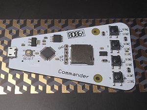
The Commander is a handheld button and LED board with accelerometer and micro SD slot with CircuitPython support.
Features
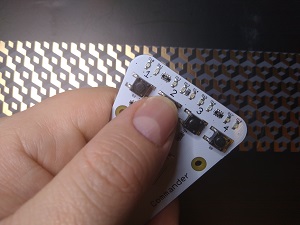
- 4 Tactile buttons
- 9 LED (red and amber LED per button and an blue LED between button 2/3)
- Accelerometer (ADXL345)
- Micro SD slot
- Atmel SAMD21G18A based with native USB
- Preloaded with USB Mass Storage bootloader (uf2-samdx1) and CircuitPython
You can get your hands on a Commander from our Tindie store or build your own using the source files below.
Commander Design/Source Files
- PCB / Schematic (Eagle)
- uf2-samdx1 USB Mass Storage bootloader
- CircuitPython
Pin Names
| CircuitPython | SAMD21G18A | Usage |
|---|---|---|
| D0(RX) | PA11 | UART RX |
| D1(TX) | PA10 | UART TX |
| D2(B1) | PA20 | Button 1 |
| D3(B2) | PA09 | Button 2 |
| D4(B3) | PB09 | Button 3 |
| D5(B4) | PA02 | Button 4 |
| D6(CS) | PA13 | Micro SD(CS) |
| D7(MOSI) | PB10 | Micro SD(MOSI) |
| D8(SCK) | PB11 | Micro SD(SCK) |
| D9(MISO) | PA12 | Micro SD(MISO) |
| D10(LED1A) | PA15 | Button 1 LED A |
| D11(LED1B) | PA14 | Button 1 LED B |
| D12(LED2A) | PA08 | Button 2 LED A |
| D13(LED2B) | PA07 | Button 2 LED B |
| D14(ALERT) | PA06 | Alert LED A |
| D15(LED3A) | PA05 | Button 3 LED A |
| D16(LED3B) | PA04 | Button 3 LED B |
| D17(LED4A) | PB02 | Button 4 LED A |
| D18(LED4B) | PB03 | Button 4 LED B |
| D19(SCL) | PA15 | Accelerometer SCL |
| D20(SDA) | PA22 | Accelerometer SDA |
Either of the CircuitPython names can be used (D18 or LED4B for example).
Usage
If you're new to CircuitPython I would advise familiarising yourself with it by looking through the guide from Adafruit. Unfortunately our patch to add support for their recommended editor Mu hasn't been accepted yet so currently use your serial terminal of choice (like PuTTY for example on Windows) and connect using speed 115200.
Examples
These basic examples show how to use the features on the Commander. If you haven't already it's worth looking through the CircuitPython Guide and CircuitPython Essentials from Adafruit.
Buttons
The following code will output "B1", "B2", etc. when the matching button is pressed.
import time
import board
from digitalio import DigitalInOut, Direction, Pull

b1 = DigitalInOut(board.B1)
b2 = DigitalInOut(board.B2)
b3 = DigitalInOut(board.B3)
b4 = DigitalInOut(board.B4)

while True:
  if(b1.value): print("B1")
  if(b2.value): print("B2")
  if(b3.value): print("B3")
  if(b4.value): print("B4")
LED
Here we create a Python dictionary to use for the LEDs, sets them as outputs and then loop through lighting up each one for half a second.
import time
import board
from digitalio import DigitalInOut, Direction, Pull

led = {}
led[0] = DigitalInOut(board.LED1A)
led[1] = DigitalInOut(board.LED1B)
led[2] = DigitalInOut(board.LED2A)
led[3] = DigitalInOut(board.LED2B)
led[4] = DigitalInOut(board.ALERT)
led[5] = DigitalInOut(board.LED3A)
led[6] = DigitalInOut(board.LED3B)
led[7] = DigitalInOut(board.LED4A)
led[8] = DigitalInOut(board.LED4B)

for i in range(0,9):
 led[i].direction = Direction.OUTPUT


while True:
 for i in range(0,9):
  led[i].value= True
  time.sleep(0.5)
  led[i].value = False
Micro SD
List files on the SD card (formatted as FAT32).
import sys
import os
import adafruit_sdcard
import board
import busio
import digitalio
import storage

spi = busio.SPI(board.SCK, MOSI=board.MOSI, MISO=board.MISO)
cs = digitalio.DigitalInOut(board.CS)
i2c = busio.I2C(board.SCL, board.SDA)

sdcard = adafruit_sdcard.SDCard(spi, cs)
vfs = storage.VfsFat(sdcard)
storage.mount(vfs, "/sd")

os.listdir("/sd")
Accelerometer
To use the Accelerometer additional libraries are needed, for simplicity download the CircuitPython Libraries Bundle and extract the lib directory to a lib directory on the CIRCUITPY drive.
import board
import busio
import digitalio
import sys
import storage
import time

sys.path.append("/lib")

import adafruit_adxl34x

spi = busio.SPI(board.SCK, MOSI=board.MOSI, MISO=board.MISO)
cs = digitalio.DigitalInOut(board.CS)
i2c = busio.I2C(board.SCL, board.SDA)


a = adafruit_adxl34x.ADXL345(i2c)

while True:
 print(a.acceleration)
 time.sleep(0.2)
UART (Serial)
The UART pins aren't populated by default but the holes are staggered to allow a standard male pin header (2.54mm) to be pushed in the holes which should be enough for testing if you don't want to solder the header.
This example echos back every character received on the connected serial interface (115200 speed), prints the characters received over the REPL interface and toggles the ALERT LED on for every character received.
import board
import busio
import digitalio

led = digitalio.DigitalInOut(board.ALERT)
led.direction = digitalio.Direction.OUTPUT
uart = busio.UART(board.TX, board.RX, baudrate=115200)

while True:
 data = uart.read(1)
 if data is not None:
  print(data)
  ret = uart.write(data)
  led.value = not led.value
